
Stereo Camera Flash Delay
For the stereo photographer
By
Mark McAndrew
Introduction
The SONY mirrorless cameras have gained popularity with stereo photographers. For some, the selection of the camera model for a stereo camera rig is not only based on cost but also the potential separation distance between camera lenses. The A5100 offers closer lens separation compared to similar models. The problem however is that some SONY entry level camera models like the A5100 don’t support external electronic flash.
For Stereo Flash photography, it is imperative to only have a single flash operating. Whilst the A5100 has a popup flash, it was found to cause problems. When a single flash is enabled, only one camera would record the flash exposure.
So, what is the problem using A5100 popup flash?
Put in simple terms, from pressing shutter release to recording the exposure there are variable timing components at play. When only one flash is enabled, the timing differs between cameras. The cameras therefore can fire at different times causing one of the cameras to completely miss the flash.
Simple testing using a single A5100 and its popup flash has revealed some interesting behaviours. In the results of the simple test shown below, the time between pressing shutter and the pre-flash is variable depending on distance to subject. In this sample measurement, the final flash fires after 142mS. Whereas the typical delay time for the shutter to open with the A5100’s flash disabled is about in the 21-23mS region!
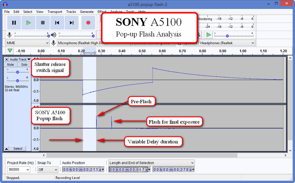
The
relationship between the shutter release in the top trace verses the
flash energy that is emitted.
Important Note: The results shown
above are derived from the Poormans Oscilloscope
Solution
The issue using flash has historically plagued stereo photographers. For some stereo camera rigs, the solution is to have a pre-determined delay before firing the flash. The delay is activated by the shutter release then firing the flash coinciding with both cameras’ shutters opening.
The Stereo Camera Flash Delay circuit was designed to overcome timing inconsistencies as well as provide support for the usage of many types of external electronic flashes.
Building a suitable timing circuit may use many different types of circuit design. Stereo Photography forums have provided many ideas to stimulate the best technology for a solution. Fortunately, one forum member, Timo Puhakka, discovered a flash delay circuit originally intended to use an electronic flash triggered by a camera’s “flash bulb” contacts This type of flash synchronisation is known as M-Sync. The M-Sync flash mode closes the contacts a few milliseconds before the shutter is open, to give the flashbulb time to reach peak brightness before exposing the film. The details for the M-Sync project can be found in the internet link below.
https://www.instructables.com/id/Electronic-Flash-M-Sync-Hack/
Design
The circuit is based on a microcontroller with a minimal parts count. The circuit incorporates a variable delay controlled by a potentiometer. The variable timing allows customisation for any flash or camera. The microcontroller used is an Atmel ATtiny85. The great thing about this processor is that it is the same physical size as the very famous 555 timer chip, yet offering a programable outcome. The other advantage of the processor is that it can be powered by 3 volts, which makes it very compatible with the SONY A5100 that also operates with a 3 volt power source. The processor also has a comparatively low power consumption enabling it to be powered by a 3 volt button battery. Programming this microcontroller was achieved by using the popular Arduino IDE software platform with special addon software specifically for ATtiny processors. The cost of the microcontroller was inexpensive. At the time of writing this account, it cost a modest $6 in Australia.
Adapting M-Sync for stereo camera operation
Despite the basic suitability of the M-Sync project for the stereo camera flash delay, a number of modifications were required to customise the design. The development of the project took place in both Canada and Australia. The initial “instructables” based prototype circuit had a number of problematic interfacing issues for both the shutter release contacts and flash operation. The list below details both modifications and developments required for stereo operation.
Modifying Circuit to run from 3volts (original M-Sync operated from 6 volts)
Alternate Opto coupler design to fire modern recent electronic flashes (to overcome lockups with some flash models)
Modifying the sketch to trigger on high to low (ground) camera shutter switch (to eliminate complex switches)
Utilising internal pullup resistor in ATtiny85 for shutter release switch port (to reduce parts count)
Adding CPU activity LED (to give user a level of confidence that unit is operating)
Adding transistor driver for the optocoupler to enable older thyristor flashes (using low reverse voltage)
Adding a separate more robust interface for older high trigger voltage electronic flashes.
Drawing revised circuits
Devising a cost-effective technique to measure the flash delay time (to confirm absolute delay time)
Produce timing measurement diagrams (screen shots using Poormans Oscilloscope to confirm the timing of the circuit)
How does it work?
The circuit detects the shutter release signal and then starts a delay timer before triggering a flash. The design incorporates a potentiometer to adjust the time delay. This enables the flash to fire at the right time regardless of camera model and flash combination.
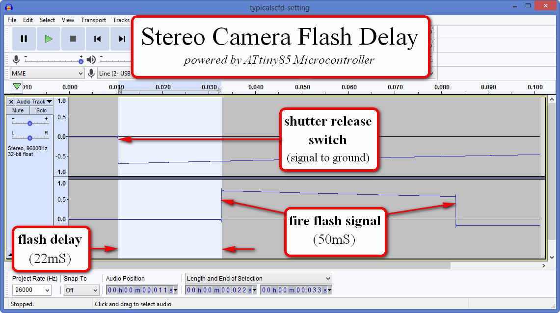
Typical flash delay measurement showing shutter release trigger signal and then fire flash signal
The measurement was recorded using the Poorman’s oscilloscope
Circuit and program description
The circuit’s hardware is very simple consisting of only a handful of components. At the centre of the circuit is a microcontroller. The microcontroller (processor) has a number of ports, some digital and the others with analogue capability. The camera shutter release signal is connected to a digital input, while the flash circuitry is connected to a digital output. An analogue input port is used to measure a signal that is utilised to calculate the flash delay. This input is connected to a potentiometer (variable resistor) to form a voltage divider which applies a variable voltage to the processor port. By adjusting the potentiometer, the flash delay time can be changed between 0-51mS.
With all the input/outputs connected, the rest of the operation of the flash delay is controlled by computer code. The code is called a “sketch”. A sketch is a high-level computer programming language that has a likeness to the C programming language yet remaining very simple. The Arduino IDE (Integrated Development Environment) program converts the sketch to machine instructions that the ATtiny85 microcontroller can understand to run the program. The program detects a negative voltage transition from the cameras shutter release signal. It then assigns a timing delay calculated by the voltage applied by the potentiometer. After the calculated delay expires, then a digital output signal is activated to apply a signal to the optocoupler. The output from the optocoupler then effectively closes the contacts of the electronic flash unit. After the flash signal, there is a delay period started. That delay allows time for the electronic flash to charge up again before it is possible to take another shot. Finally, to have confidence that the computer code is running, an additional digital output port is connected to the “activity LED” that flashes briefly every 5 seconds. The heart of the activity LEDs sketch component, is code that uses a special command called millis. If the normal delay command was used, then execution virtually stops for that command. In contrast, the millis command reads the processors clock value each pass through the loop of the code lines under void loop() statement. It checks the clock value to know if it is time to turn led on or off allowing continued execution of the stereo camera flash delay code.
Prototype testing results
Testing the stereo camera flash delay has revealed some interesting results. The understanding of the circuit’s operation was greatly demystified by using oscilloscope functionality. This functionality was created very economically by using a computers sound card and a very simple interface circuit. It is referred to as the “Poormans Oscilloscope”, based on a concept published by Rob Crocket. Whilst it is far from perfect, it does allow pretty good timing measurements. For more information. Link Here
Initially testing was conducted with a single SONY A5100 camera. It demonstrated that the delayed flash concept worked but the results varied slightly between flash units. There were further differences after changing the flash power levels.
First round of testing - Single camera “pushing limits”
Test
1.1
delay
time = 21.26mS, YN660 power 1/16
Shutter
speeds 1/125 ok... 1/160 ok... 1/200 ok ... 1/250
NG (bottom
3rd of frame not exposed by flash)
Test
1.2
delay
time = 21.26mS, YN660 power ¼
Shutter
speed 1/160 ok ... 1/200
NG (bottom
1/8 of frame not exposed by flash)...
second attempt 1/200 OK
Test
1.3
The
camera was moved by a couple of degrees pointing to a different
subject
delay
time = 21.26mS, YN660 power ¼
Shutter
speed 1/200 ok... 1/250 ok... and again 1/250 ok... 1/320
NG (bottom
half of the frame not exposed by flash)
Test
1.4
delay
time = 21.26mS, YN660 full power 1/1
Shutter
speed 1/320 ok ... 1/400 ok ... 1/500
NG (half
frame not exposed by flash)
Test
1.5
delay
time = 21.26mS YN660 full power 1/1
Moving
to a subject about one metre away.
Shutter speed 1/400 ok ...
1/500
NG (top
third of the frame not exposed by flash)
Second round of testing - Stereo cameras tested
This round of testing was done on a more conservative basis compared to previous tests. Since the published flash synchronisation speed for the SONY A5100 is 1/160sec, it should be the safest test benchmark.
Test parameters:
The potentiometer delay value was changed (for no particular reason) to 23.3mS (equating to a trimpot resistance WRT ground of 47.1KOhms) A single remote shutter release (Promaster) was connected via a diode network to two A5100 cameras. The flash delay circuit was connected to the shutter release wire from the Promaster remote. The A5100's were set to Manual mode with a shutter speed of 1/160sec. The YN660 test flash was set to mainly higher power levels during tests.
Results:
Over 95% of test shots with the flash delay were successful. Both cameras recorded complete frames exposed by the flash. That also included different subject distances and flash power ranges. For the couple of shots that failed to record a full frame, it seemed to be related to not allowing enough time for the Auto focus process to finish. (It seems that problem is the same issue as achieving accurate sync between cameras!)
Third round – checking the timing ranges for different flash combinations
The reason for this round of testing was to determine timing delay tolerances according to different flash types and power combinations. There was a curiosity about finding the best position for the potentiometer setting. The problem with the multi-turn potentiometer is that you can't visualise its actual position. It was important to get some idea what the extremes of the delay window times would be for a full “Flash exposure” on both frames of the stereo pair. To achieve the measurements, it required that the multi-turn pot was temporarily replaced with a conventional rotary one.
The measurement procedure:
Camera settings - Manual mode, shutter speed 1/160sec, ISO 100 and normal evaluative auto focus
The potentiometer was to set to a nominal position then the timing value result was checked. Once both frames were properly exposed by the flash, the pot was adjusted either side to check when partially exposed images would appear. These delay time extremes were recorded via the Poormans oscilloscope to determine the "effective delay range". See the summary of results below.

The single turn potentiometer used for testing possibly impacted the accuracy of the results. Its internal wiper on the carbon track would have a different resistance at the same position. This was evident when changing the position between clockwise and anti-clockwise movement!
Conclusion:
The measurements prove that the average delay time varies slightly between different flash type/power settings! So, if you wanted to use different flashes you would need to determine a "sweet spot" to suit.
Field testing results
Timo was the lead for this testing. The first test using his favourite flash worked without having to adjust the trim pot. The circuit worked with the trimpot position as it was from factory!

SunsetFlashTestX.jpg
This image was shot 1/160th, f8.0, ISO 400 using Timo’s Vivitar 1200 at the second weakest setting.
Note:-Flash synch become unreliable above 1/160th.
Timo took a nice flash image of his son’s home-grown jalapeno peppers to make a batch of hot sauce. It’s a great comparison of the naturally lit shot and the flash shot. Oh yes, there may be a few cherry tomatoes that were added for colour!

PeppersNaturalLight.jpg

PeppersUnderFlash.jpg
How to build the Stereo Camera Flash Delay
In general, this project is very simple, but only when it is finished!
The project will require patients and care along the way. You will need to apply some of your existing skills or be willing to learn new ones.
Do you have sufficient computer confidence?
Do you have any electronics background?
Can you solder?
Do you have a simple test tool such as a mulitmeter
Also, before you build this project, it is essential to select/test and build the correct flash interface circuit suitable for your flash. Failure to do so may destroy the optocoupler. (Yes, you will need to read “flash considerations” in the hardware section!)
Going further – It is assumed the people that may take on this project may require additional background information. The information below is what was helpful in my own learning experience.
Recommended reference book:
Programming Arduino: Getting Started with Sketches ISBN 978-0-07-178422-1
ATtiny85 Quick Reference
This describes a summary of the software commands and a description of
the hardware connections. It is a PDF document that can be
downloaded from the sparkfun.com web site
Timing measurements with the aid of an
oscilloscope.
Oscilloscopes are the ultimate “eyes” for electronic circuits.
Unfortunately, they are also expensive. There is a cheap alternative,
“The Poormans Oscilloscope” LINK here.
If you are comfortable with all these points, welcome to the exciting journey ahead!
Software build
There are many methods to program the Atmel ATtiny85 microcontroller. The device used for programming the Stereo Camera Flash Delay is a Sparkfun AVR programmer. This is a purpose build programmer which does not require any additional components. It plugs directly into your computers USB port.
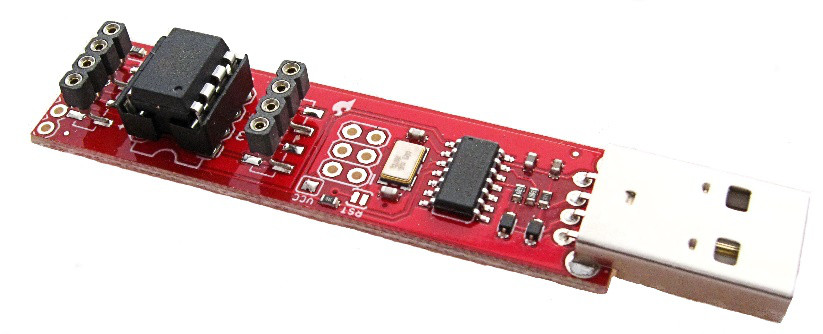
Tiny AVR Programmer: PGM-11801
An ATtiny85 chip can be seen plugged into the programmer (left side)
-
Computer
-
AVR programmer PGM-11801
-
AVR programmer setup instructions
The
link to the “programmers
hookup guide”
is very comprehensive. It covers all aspects to both setup the
computer software environment and to program the ATtiny85. The
“hookup
guide” is
quite a long document. It covers many different circumstances and
also has sections dedicated to troubleshooting. There is only one
critical omission in the document. See
the missing
vital instruction step
below.
Since
both the computer and programmer setup instructions could be a little
overwhelming, here is an overall summary of the main tasks.
(Something that is not
clear in the hookup guide).
Load Drivers - Only required for Windows, not required for MAC and Linux
Install Arduino IDE software (version used in this documentation - Windows version 1.8.12)
Add special extra software/files for IDE specifically for ATtiny85
The missing vital instruction from hookup guide Set 8MHz clock and then “burn bootloader”
Recommended first sketch (Blink) This will ensure that the programmer is functioning and ATtiny85 works.
Loading/uploading the stereo camera flash delay sketch
The procedure to setup and use the PGM-11801 has been tested in both the Windows and a MAC computer. It takes some time to load all the required software, so be patient!
The hook-up guide’s missing vital instruction relates to making a one-off setting in the ATTiny85 which is essential for correct operation. In the Arduino IDE setup procedure, when you come to select your board type, processor type and speed, an additional step is required. Incidentally, make sure the programmer is plugged into the USB port with the ATtiny85 inserted in the socket!
The brief explanation follows: -
By default, a new ATtiny85's chip comes with its internal clock running a frequency set to 1MHz. The stereo camera flash delay software is designed to run with an 8MHz internal clock. It is essential that you select 'Internal 8MHz' clock, and then “Burn Bootloader” from the Arduino IDE Tools menu. This operation changes what is referred to as a “fuse” called CKDIV8 - Divide Clock by 8. from value 0 to 1 (effectively disabling the divide by 8 from clocking).
The final step in software loading process is to load the Stereo Camera Flash Delay sketch. This is a two-part process. The first part is where the sketch is compiled into machine code instructions ready for uploading into the ATtiny85 microcontroller (see Verify below). The second part is to Upload the machine code program instructions into the ATtiny85’s internal flash memory.
Stereo
Camera Flash Delay sketch Text file Download Here
Note: - The screenshots that have been included in this instruction below only shows when the process is working correctly. It would be difficult to describe all the possible “twists and turns” in this document!
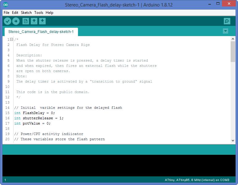
When you first start the Arduino IDE, you will see a screen like this.
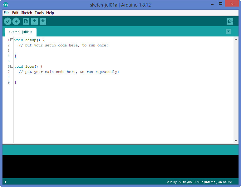
Select and delete the existing lines of code, then paste the stereo camera flash delay sketch text file in its place.
It is probably a good idea to save the sketch for later use. The special tip when saving the sketch is that the filename must not contain any spaces!
From the main menu File > SaveAs
The sketch will be saved as an “.ino” file in your documents directory.

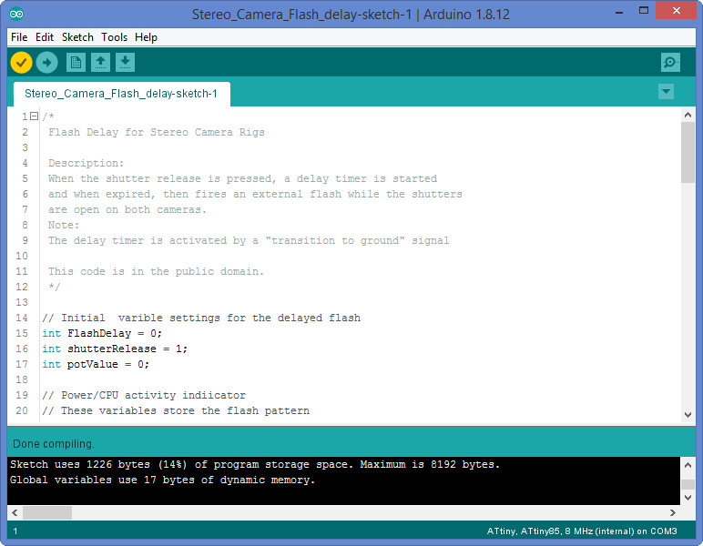
After pasting and saving the code, the next step is to verify the sketch code.
To start the “Verify”, click on the “tick” icon (top left) or from the main menu Sketch > Verify/Compile
The verify process uses the lower part of the screen and is very useful to see how the sketch is checked and compiled. If there are no errors, it will report the memory usage statistics relating to your sketch. In essence the compiler successfully translated the sketch into code that the ATtiny85 can understand and run. If any errors are reported, then maybe some syntax errors exist. Ensure that all the curly brackets at the bottom of the file are included.
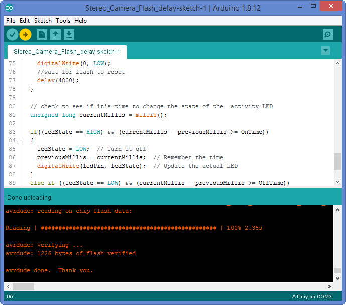
The final Arduino IDE action is the “Upload”. This is where the code is actually uploaded (programmed) into the ATtiny85 microcontrollers flash memory. Make sure the programmer is plugged in before attempting the upload! The upload consists of two activities. It does the verification and compiling action (again) and then transfers the compiled binary code into the ATtiny85’s flash memory. The reason why the result reports “avrdude done”, is attributed to the underlying utility program to download/upload/manipulate the ROM and EEPROM contents of AVR microcontroller. The term AVRDUDE is an acronym AVR Downloader/UploaDEr. While we are explaining terms, AVR is Advanced Virtual RISC. The term RISC is Reduced Instruction Set Computer!
To start the “Upload” click on the “right arrow” icon (top left) or from the main menu Sketch > Upload
Remove the programmer from the computer USB port then the ATtiny85 chip can be removed from the programmer ready for use.
Hardware build
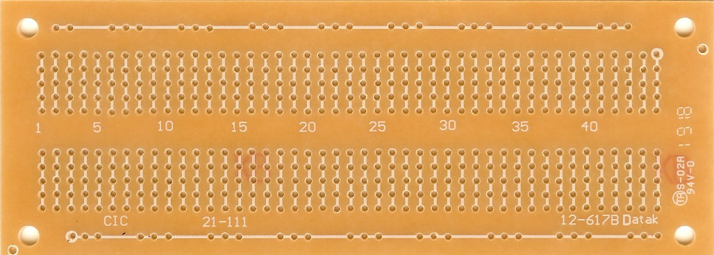
Building the hardware is relatively simple. The construction technique will depend on your own requirements. It is recommended, however, to use some sort of “breadboard” printed circuit board and cut it down to the required size.
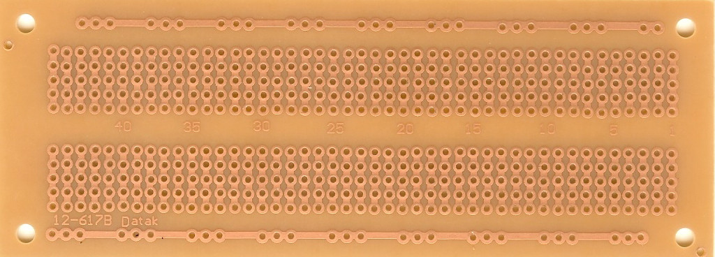
Copper side (solder side)
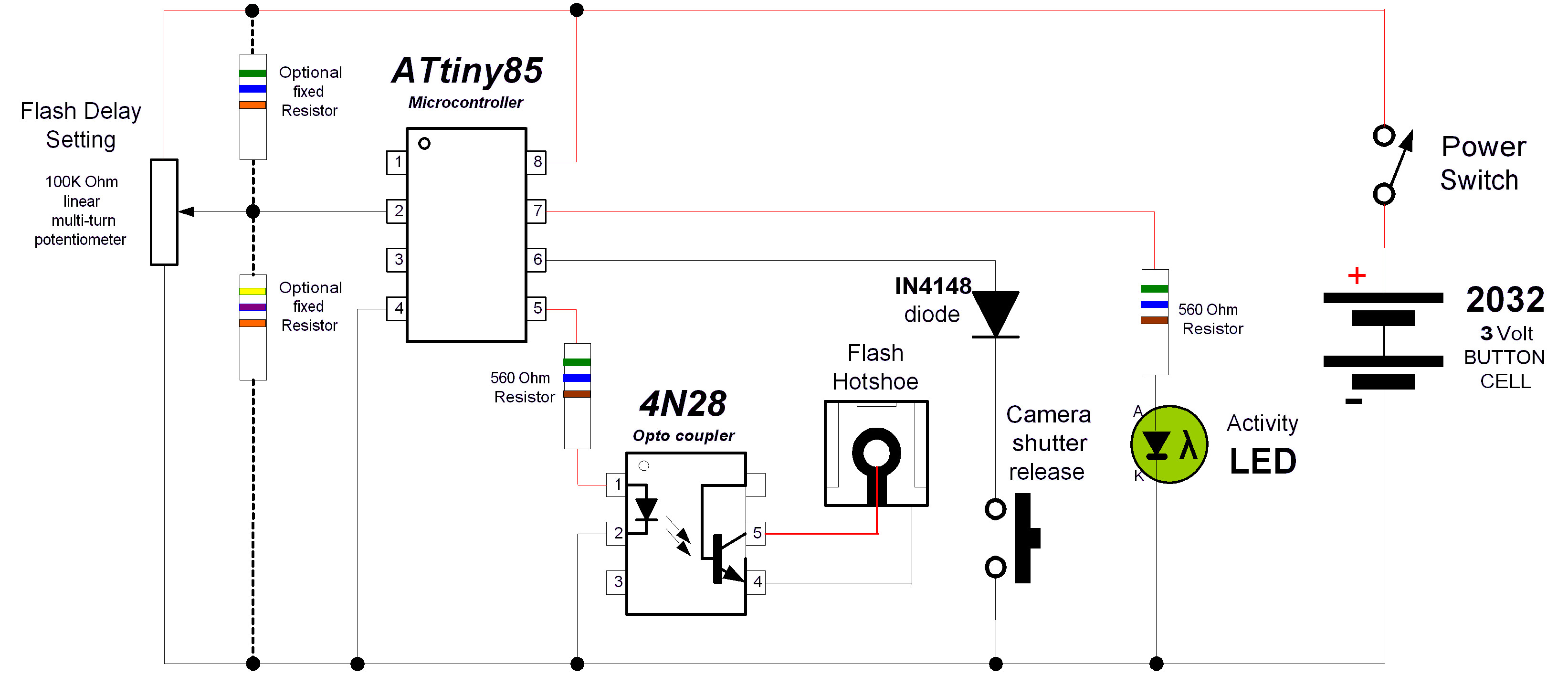
Circuit Diagram
The basic circuit diagram is shown below. This design is only suitable for low trigger voltage electronic flashes. It is compatible to most newer flash units manufactured in recent years. Depending the age of the flash, and its electrical characteristics, different connection interfaces are required. Alternate flash connection interface designs are described in the Hardware variations section.
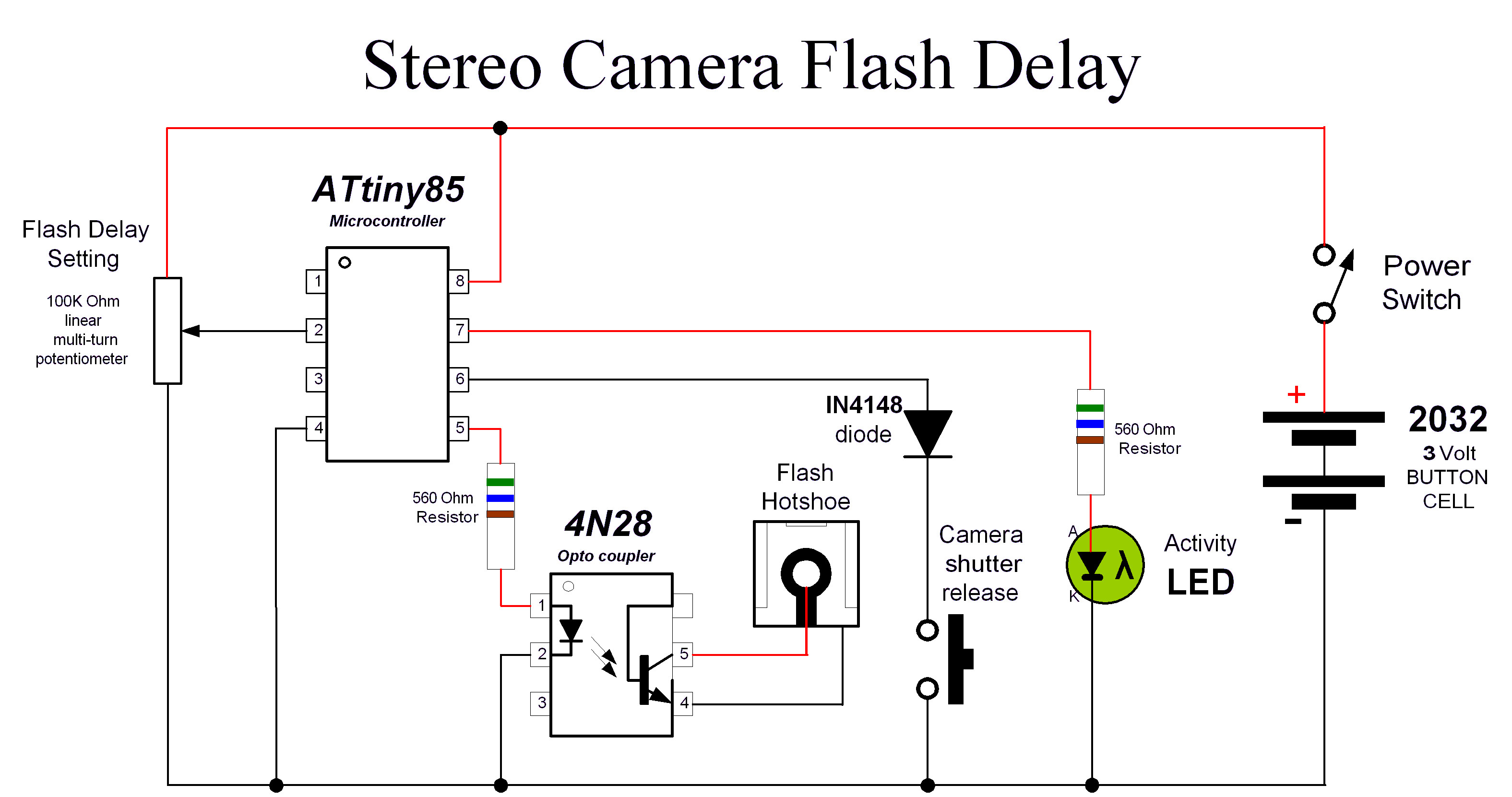
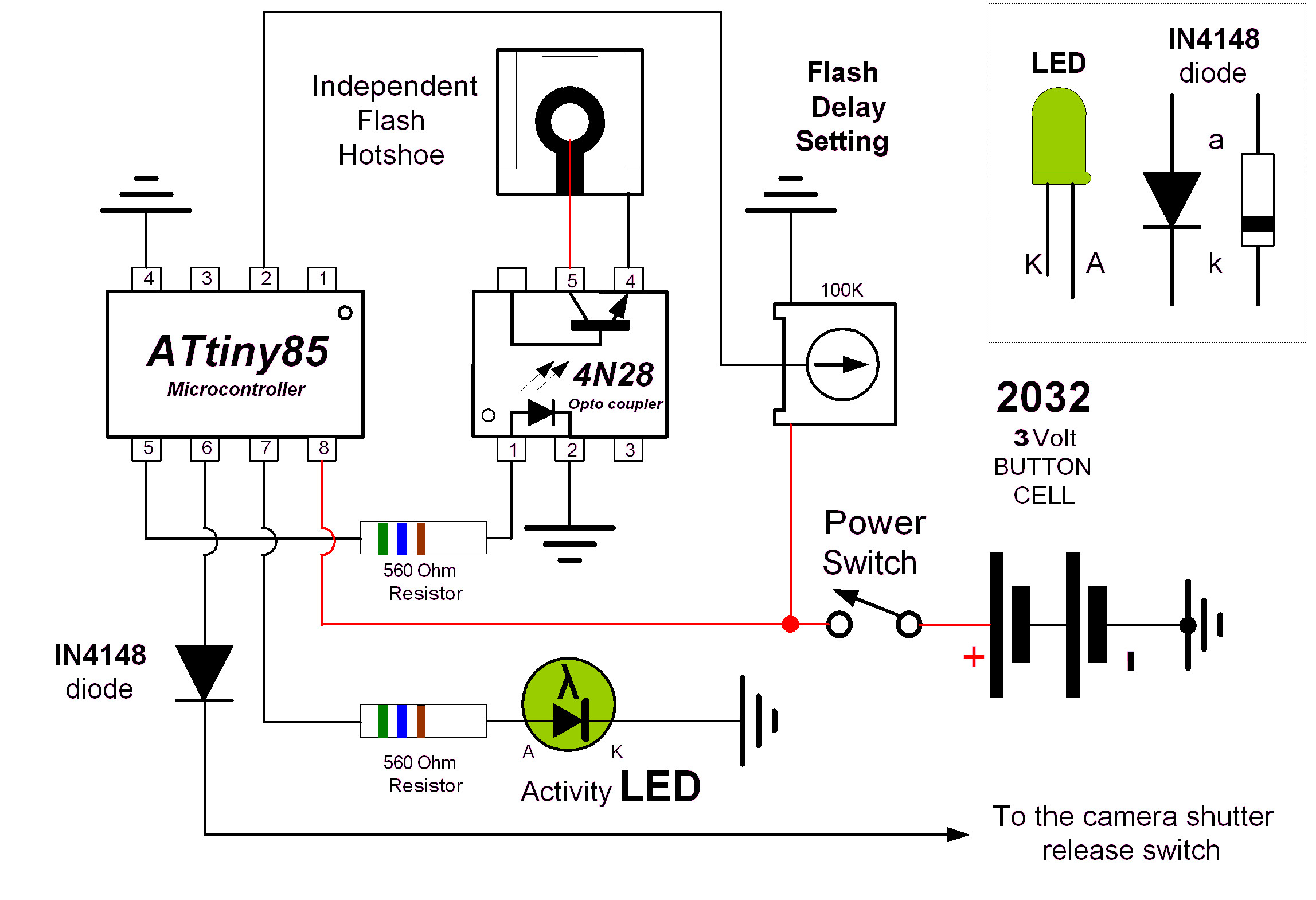
For some constructors, seeing such a diagram and then trying to translate in to a physical layout could prove difficult. To assist, here is another version which may be more suitable to see a layout to suit a breadboard PCB.
Parts list
Atmel
ATtiny85 microcontroller (8pin)
Optocoupler
either 4N28 or MOC3021 (depending on the
flash
type)
100k
ohm potentiometer (either multiturn or single
turn) trimpot
2 x
560 ohm resistors
1 x
Green LED (or any colour that you like)
3
volt
battery such as 2032 button cell (It could be
any battery configuration that supplies 3volts)
1
x 20mm button cell vertical Battery holder –
or similar
1 x
small switch (Power switch)
1 x
IN4148 diode (providing electrical isolation
from the cameras shutter release signal)
1 x 8
pin IC socket (optional - but recommended for
the ATtiny85)
1 x 6
pin IC socket (optional - but recommended for
the 4N28 or MOC3021)
1
x Breadboard prototyping board
If
using the transistor driver for the MOC3021, the following additional
parts are required. (see
more information under hardware variations)
1 x
BC548 NPN transistor
1 x
4.7K ohm resistor
1 x
100 ohm resistor
If
you are using the MOC3021 without the transistor driver. (see
more information under hardware variations)
1 x
220 ohm resistor
If
you require a high trigger voltage interface. (see
more information under hardware variations)
1 x
C106D1 Silicon Controlled Rectifier (400v 4A)
1 x
220nF greencap polyester (100v) or monolithic (50v) capacitor
1 x
6.8M ohm resistor
1x
270K ohm resistor
1 x
1K
ohm resistor
1 x
220 ohm resistor
Note: Resistor power rating may be either 0.25 or 0.5 watts
Hardware variations: – Flash considerations
Caution:
You must first understand the type of flash to be used. Is the sync trigger a low voltage or high voltage?
If you have looked at the original M-Sync circuit, you would have noticed that it uses the photo triac optocoupler (MOC3021). You might then ask why has a transistor optocoupler (4N28) being used as a first choice. The answer is simple. When testing the first prototype, it was found that the flash would only fire once. Subsequent flash operation was only possible by breaking the circuit between the flash and the MOC3021 device. To overcome this situation, a change was made to a transistor optocoupler. The only issue is that photo transistor optocouplers can only tolerate low DC voltages as opposed to MOC3021 that is rated for 400volts peak DC or 280volts AC.
It is therefore important to determine the choice of Optocoupler for the flash connection, either photo transistor or photo triac output. If the flash has been manufactured in the last few years in the digital photography era, it should be a low voltage at the hotshoe and comply with international standard ISO10330:2002. In addition, unlike using the MOC3021, the 4N28's connection to the flash is polarity sensitive, so it is important to also determine the polarity of the trigger voltage. If the “ready” indicator on the flash is a neon indicator, then it is more than likely an older high trigger voltage flash. A high trigger voltage flash should not be used directly with the 4N28 optocoupler. See the high trigger voltage flash interface option.
A simple test is required to test the hotshoe terminal voltage of your electronic flash. This could also be referred to as the “open circuit trigger voltage” of the electronic flash. If the flash unit is a more recent model (low trigger voltage), then using a cheap digital meter will be sufficient. For older high trigger voltage flashes, it becomes a little trickier. There is a measurement complication due to high impedance that is inherent with high trigger voltage flashes. This potentially impacts the accuracy of the voltage measurement depending on what type of multimeter is used. This issue is discussed further in the text below.
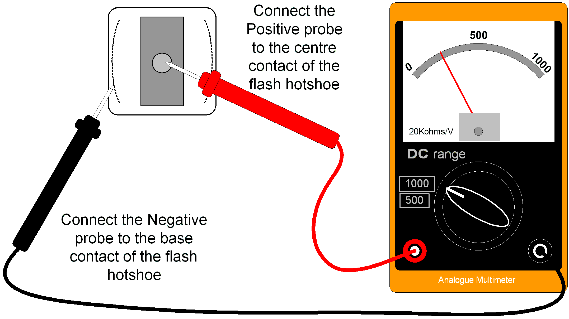
To make the hotshoe voltage measurement, use a multimeter set to a DC voltage scale. If your meter is auto ranging, just set it to DC. Alternately, manually set the meter to highest DC voltage scale. Turn the flash on and wait for the ready/charged light. Measure the hotshoe voltage with the meter connections shown in the diagrams below. Some flashes have multiple pins, so make sure you test the right one! Make sure you don’t touch the terminals with your hands. Older flashes may expose a very high voltage which could give you an electric shock! If the meter is displaying a low voltage, set the meter to a lower range to improve the measurement accuracy.
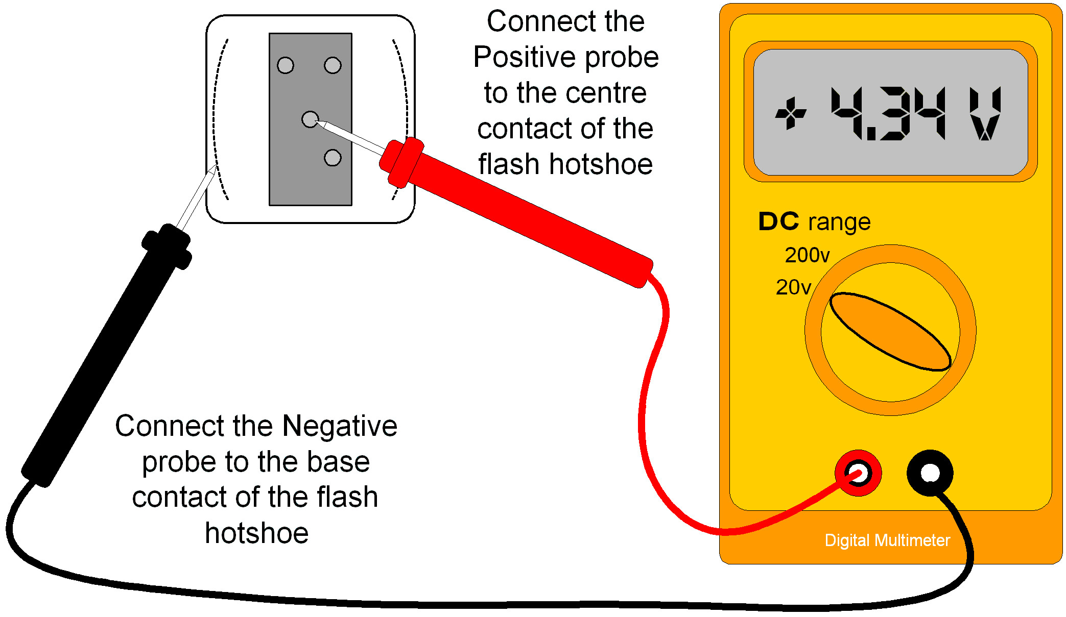
Hot shoe connection shown here is for a Nikon configuration
If the voltage is less than 20volts then the 4N28 optocoupler would be your choice. If the voltage is higher or negative, it would be more suited to using either the photo triac MOC3021 or the high trigger voltage flash interface using a silicon-controlled rectifier device (SCR) C106D1.
Measuring older high trigger voltage flashes requires a little more explanation. It was mentioned earlier that the high voltage flash circuitry also has high impedance or resistance. This means that the meter that you use to measure must also have high resistance. The meters resistance can normally be determined by checking the meters’ manual. For more accurate measurements the meters’ resistance needs to be much higher than the impedance of a typical flash circuit. Using a low resistance meter basically loads down the flash circuit and therefore the measurement will report a much lower voltage than the real voltage present.
Measuring high trigger voltage flashes with neon ready indicators
There are a number of different measurement methods. The simplest is to use an analogue multimeter. These meters often have a variable impedance depending on the test measurement range selected. Typically, a 20,000Ω/volt meter set on the 1000v range has an impedance of 20MΩ which is better than most low-cost digital meters that may only be 1MΩ.
If this concept is becoming complicated to comprehend, then the following example may help explain the possibilities for a vastly different range of voltage measurements. For a disposable camera flash, the measured trigger voltage using the digital meter with impedance 1MΩ was -51 volts. Whereas, the same measurement using the analogue meter was -240 volts. A big difference!!
The table below shows of results for voltages measured on various electronic flashes that were checked. They are mostly flashes built in the digital era of last 10 years. Some thyristor flashes from the film days requires the MOC3021 and transistor driver. The older Sunpak, Metz and Quantaray flashes with the high voltages require the High Trigger voltage Flash interface that is described in text below.
|
Electronic Flash model |
Voltage |
|
Yongnuo YN-660 Flash |
+2.9v |
|
Samsung SEF580 flash (outsourced to Metz!) |
+4.36v |
|
Metz 24AF |
+4.23v |
|
Godox TT350 |
+2.8v |
|
YinYan CY-32TWZ |
+7v |
|
W&S Mini flash |
+5.27v |
|
Aputure HN100 LED ring flash |
+3.24v |
|
Achiever TZ250 thyristor flash |
-5.75v with 1MΩ digital multimeter -8.75v with a high resistance meter |
|
Quantaray QB-6500A Thyristor |
+3.19v with 1MΩ digital multimeter |
|
Vivitar 2500 Thyristor |
+12.59v with 11MΩ digital multimeter |
|
Disposable camera flash – with neon ready indicator Note: The flash storage capacitor develops 341volts when powered only by a 1.5volt AA battery! It does however illustrate the potentially very high voltages within the electronic flash units. |
-51.0v with 1MΩ digital multimeter -240v with 20M ohm analogue meter |
|
Sunpak auto 114 with neon indicator |
+41.9v with 1MΩ digital multimeter +260v with 20M ohm analogue meter |
|
Metz Mecablitz 34 BCT 2 (the big boy) |
+212v with 11MΩ digital multimeter |
|
Metz Mecablitz 303B L23BL |
+181v with 11MΩ digital multimeter |
|
Quantaray QB-350 |
+291v with 11MΩ digital multimeter |
|
Wireless Flash Trigger models |
Voltage |
|
Hähnel CAPTUR |
+2.02v |
|
Yongnuo YN-560 TXII |
+3.2v |
|
Yongnuo RF-603 |
+3.03v |
|
Aputure Trigmaster II |
+3v |
The measurement techniques and issues for high trigger voltages are more fully explained in an article published by an Australian Electronics magazine called “Silicon Chip” with the title “Safe-T Flash” in the April 2008 issue.
Note: A small fee is required to download the back issue.
If you require more information and testing techniques for electronic flashes, this is a good reference link
http://dpanswers.com/content/genrc_flash_measuretv.php
To be very sure and gain confidence with your project, you can construct any prospective circuit using a breadboard. The advantage with a breadboard, is it possible to wire up without soldering any components. It is better to confirm the circuit before any disappointment when the flash does not fire.
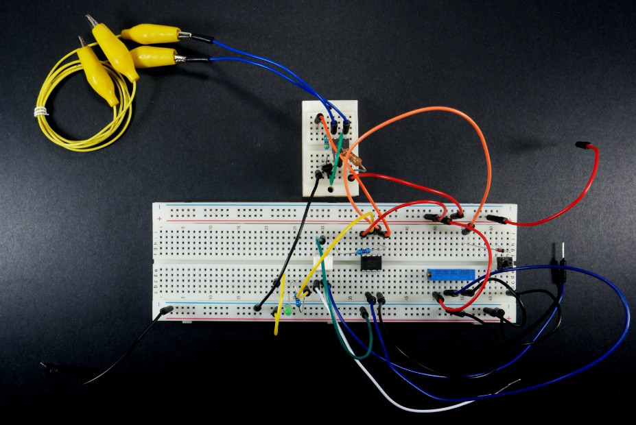
The
prototype Stereo Camera Flash Delay on breadboard.
The small
breadboard at the top was used to test the transistor assisted
MOC3021.
The test setup below shows a scenario for a low trigger voltage flash. The selection of the 560Ω resistor was based on the minimum working current value with the Yongnuo flash. It would also work with the lower value 220ohm resistor. (as used in the original M-sync project)
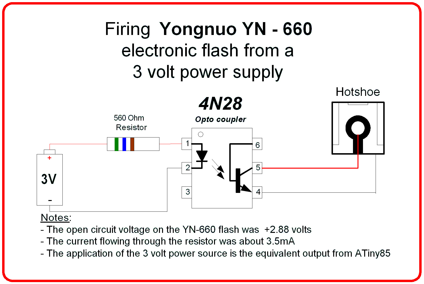
Test circuit to check the suitability of the 4N28 optocoupler
If there is a higher voltage or negative voltage then you will need to change the optocoupler to a photo triac MOC3021. If the flash is an older model such as a thyristor flash from the film days, the optocoupler may need a higher current to operate the internal LED photo diode. Whilst the ATtiny can supply a higher current to operate the photo LED diode, it is wise to use a transistor driver. The circuit below shows such an interface. The secondary advantage with this interface is that it allows simultaneous connections for both the 4N28 and the transistor driven MOC3012 providing both outputs at the same time!
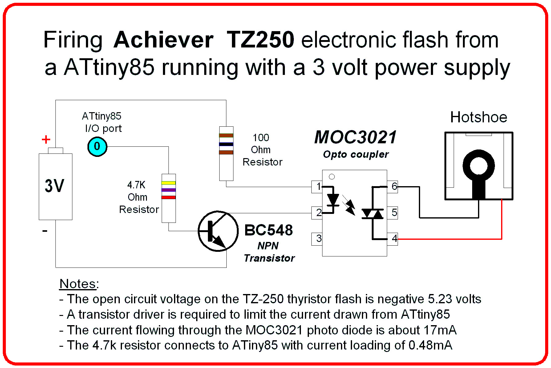
Interface circuit suitable for a thyristor based electronic flash
It is also possible to use the same components/circuit details as used in the original M-Sync project. Change the 560 ohm to 220 ohm resistor for driving the MOC3021. Reducing the resistor value further is not advisable, use the transistor driver.
After reading this description, you may wish to try the photo triac as a first choice. Later subsequent testing of flash units reveals that the MOC3021 with 560 ohm resistor can trigger the Metz 24AF and Yongnuo YN-660 flashes. So, the choice is yours!
If the flash is an older model with a “neon” ready indicator and has a high trigger voltage, then the circuit design needs to be more robust for the higher voltages and higher currents. The circuit shown below is based on a design adapted from an electronics magazine project. In fact, this circuit could be deployed in its own right to bring back to life that old flash with any digital camera with a hotshoe!
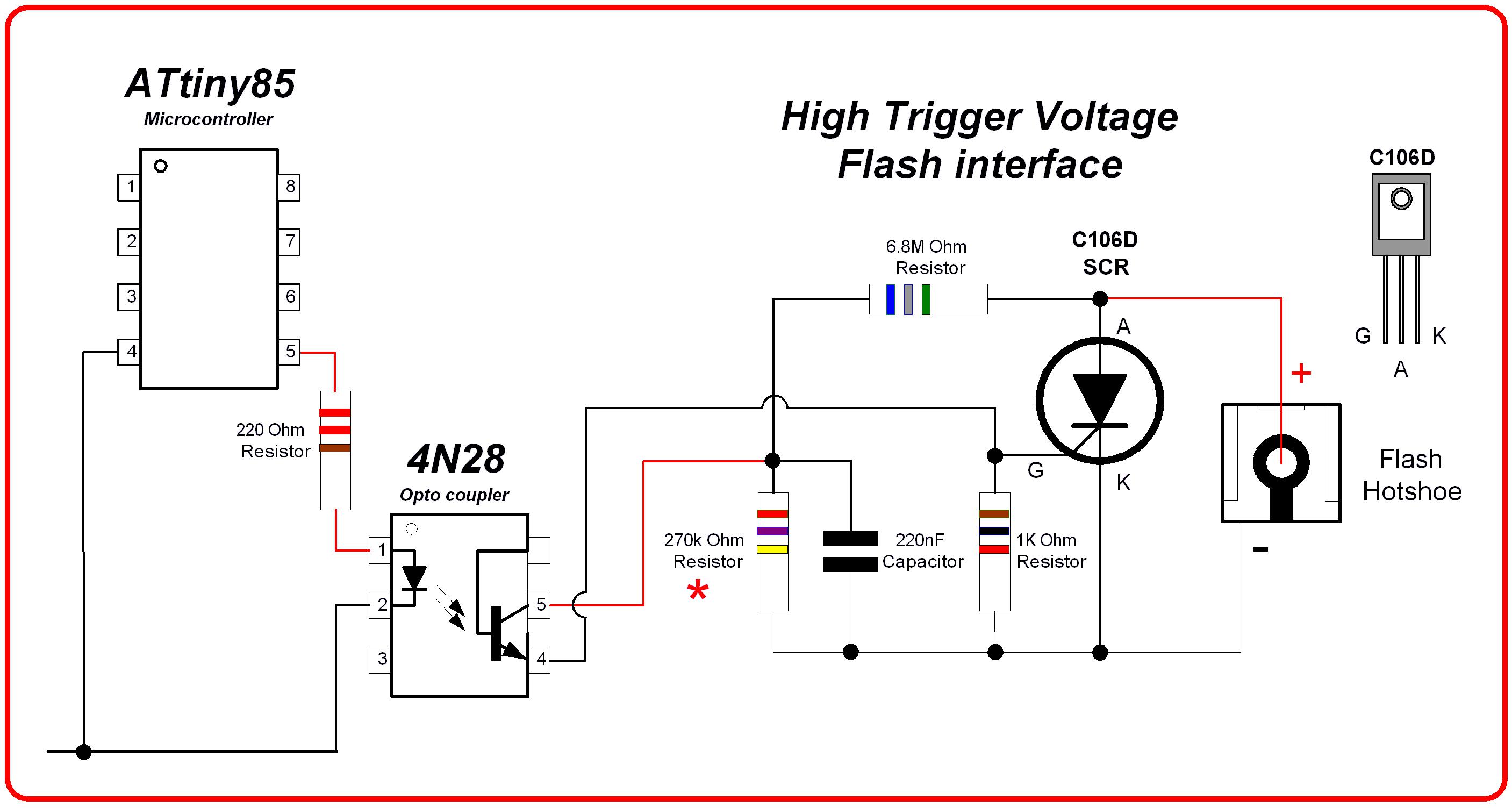
ATtiny85 connected High Trigger Voltage Flash interface based on a “Silicon Chip” circuit April 2008
The circuit operation is relatively simple. The 6.8M ohm and 270K ohm resistors form a voltage divider which charges the 220nF capacitor with power derived from the electronic flash. The voltage across the capacitor is lower compared to the original high trigger voltage. When the optocoupler is activated from the ATtiny85 (pin 5), the 220nF capacitor discharges into the gate of the Silicon controlled Rectifier (C106D), effectively shorting out the hotshoe contacts allowing the flash to fire. The 1K ohm resistor is to prevent false triggering.
The 270K ohm resistor marked by an asterisk in the circuit can be a different (lower) value to control the voltage presented to the optocoupler. For example, based on the disposable camera flash, the voltage across the optocoupler is about 6 volts. If the 270K resistor is changed to 180K ohms then the voltage is about 4.6 volts. Both resistor values work. The resistance value depends on the trigger voltage of the flash that you are using. See the measurement procedure below. If you keep the voltage across the photo transistor in the vicinity of 5 to 7 volts it is well within the specifications of the optocoupler. There is one more change to the original stereo camera flash delay circuit. The 560 ohm resistor between ATtiny85 pin 5 and the optocoupler pin 1 needs to be changed to a value of 220 ohms.

High trigger voltage flash interface prototype connected to a disposable camera flash
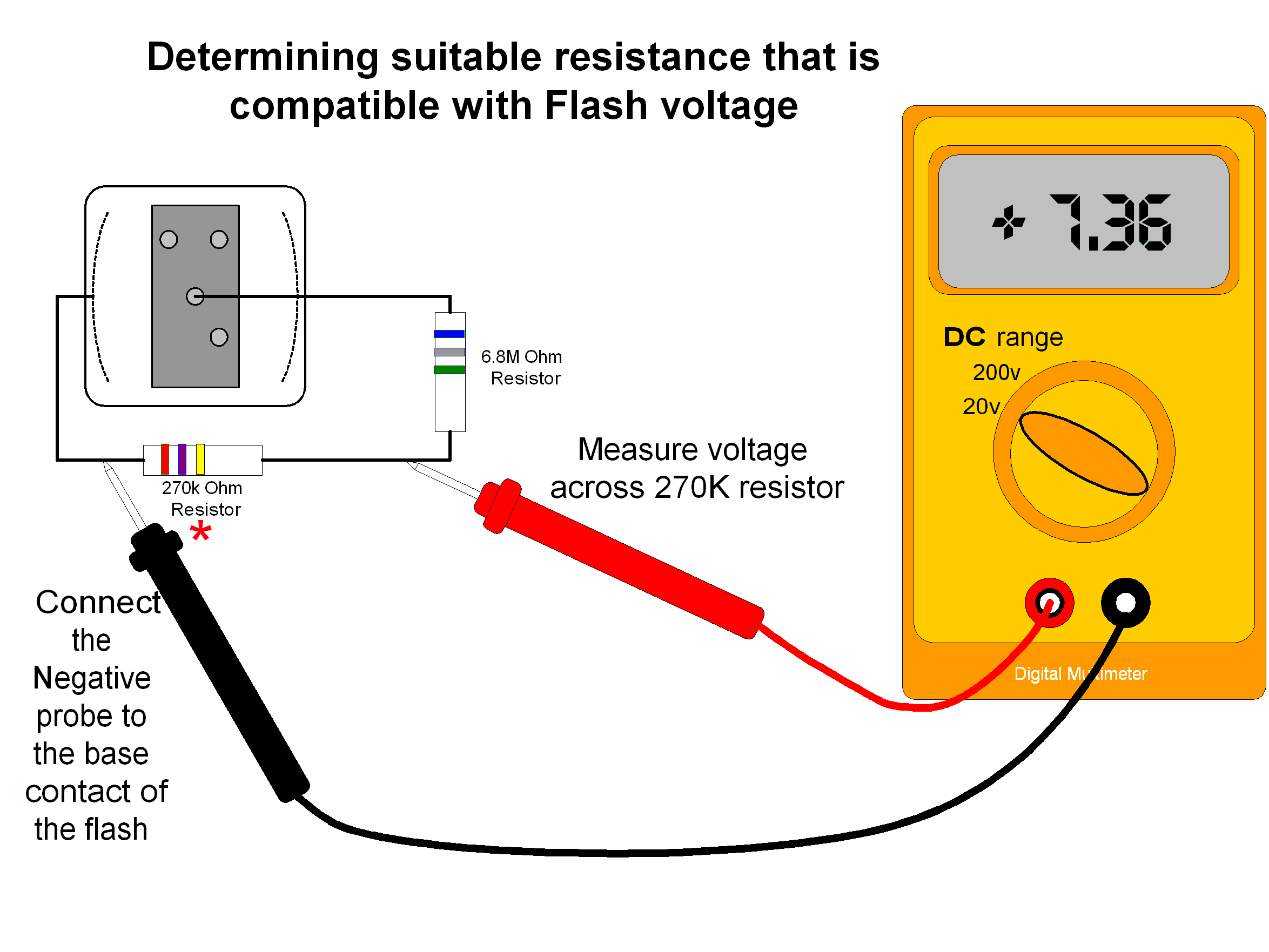
As previously mentioned, it is wise to check the suitability for the 270K ohm resistor. Use the simple test below to check the voltage across the 270K ohm resistor. If the voltage is above 10volts, then a lower resistance value may be a better choice.
If you choose to construct this as a standalone circuit for a different camera, all that is required is to reconnect the wires that were connected to the optocoupler to your cameras hotshoe or X sync contacts. See the modified diagram below. The only caution is that the voltage that is measured across the 270K resistor must be less than 6 volts for Canon and Olympus cameras. In any case, check camera specifications just to be sure!
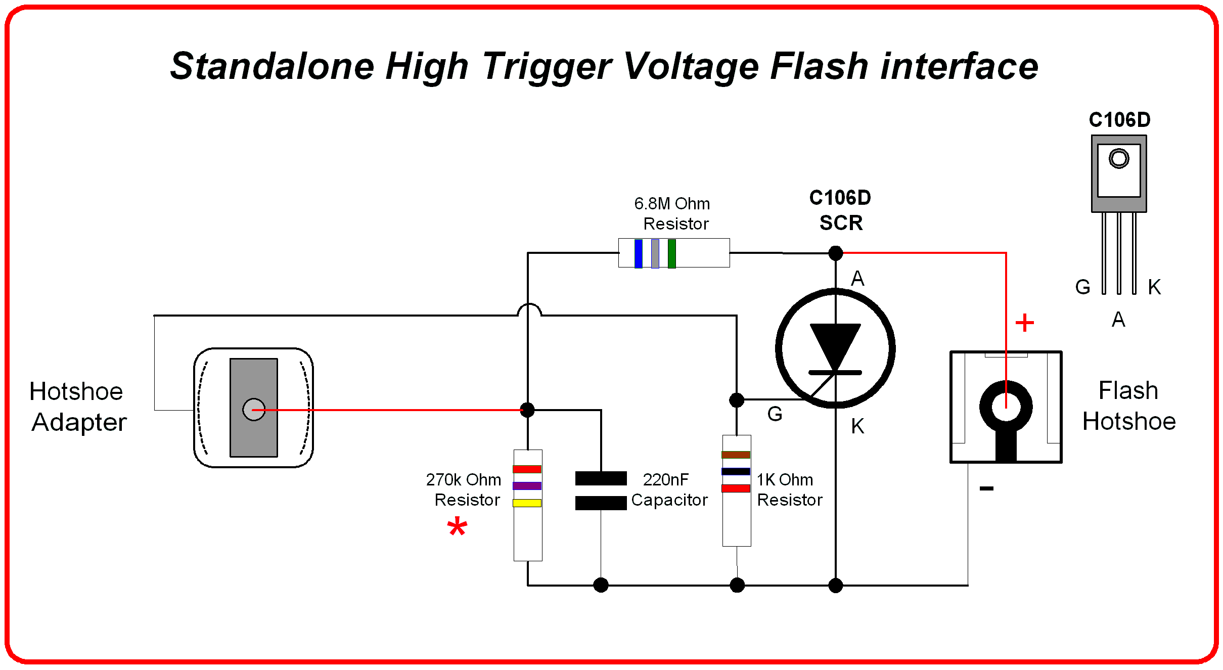
Standalone High Trigger Voltage Flash interface based on a “Silicon Chip” circuit published in April 2008
Construction details
The hardware construction will take a little time, despite the simplicity of the circuit.
Gather the components required. If you are new to electronic construction, it is important to select the correct component values.
For example, resistors values are colour coded. Depending on the technology of the resistor, it may have either 4 or 5 colour bands. The colour code value shown in the circuit diagrams are typical for a 4-band resistor. The fourth band not show on the circuit diagrams. It is used to specify the resistor tolerance. If you are using 5 band resistors, care must be taken to read the colour bands in the correct order. If there is any doubt, use a multimeter set to the “Ohms” scale to verify its resistance value.
Diodes and LED’s are polarity sensitive. Ensure that the physical orientation of the Anode (A) and Cathode (K) leads matches that of the circuit diagram.
It is recommended that you use IC sockets for both the ATtiny85 and the optocoupler. The orientation for both ATtiny and optocoupler is extremely important. As a guide, pin 1 normally has a small circular maker. If in doubt consult data sheets. There is zero tolerance for incorrect orientation. If it is wrong, then the device will device will be permanently damaged!!!
If you are also constructing the high voltage flash interface, the selection of the capacitor may be confusing. Capacitors come in both different technologies and sizes. It is possible to have the same value, yet being a different size. The size of the capacitor is normally determined by the voltage rating. The higher the voltage rating, the larger the size of the capacitor. The 220nF capacitor may be either a greencap polyester or a monolithic type. For the most compact physical design, the monolithic capacitor is much smaller than the greencap. Most capacitors have their value stamped on the casing. It may be the exact value or it can also use the EIA coding standard.
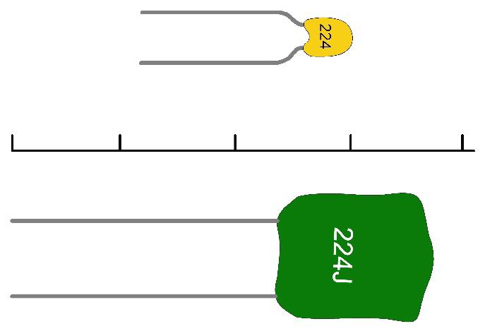
Capacitor size comparison between greencap and monolithic
The centre scale marker is in cm and the capacitor value is shown using the EIA coding scheme
If you are constructing the “MOC3021 transistor interface, care must be taken to identify the physical connections to the transistor. Transistors come in a number of different physical packages. Be sure to consult the data sheet from the supplier to determine the correct pinouts.
Solder the passive components first. This would include the IC sockets resistors, any wire links to interconnect different tracks and external wire connections. Then solder the active components such as the diode and LED.
After wiring is completed, check you work to make sure all connections and your solder joints between the components are correct. It is better to check your connections before applying power!
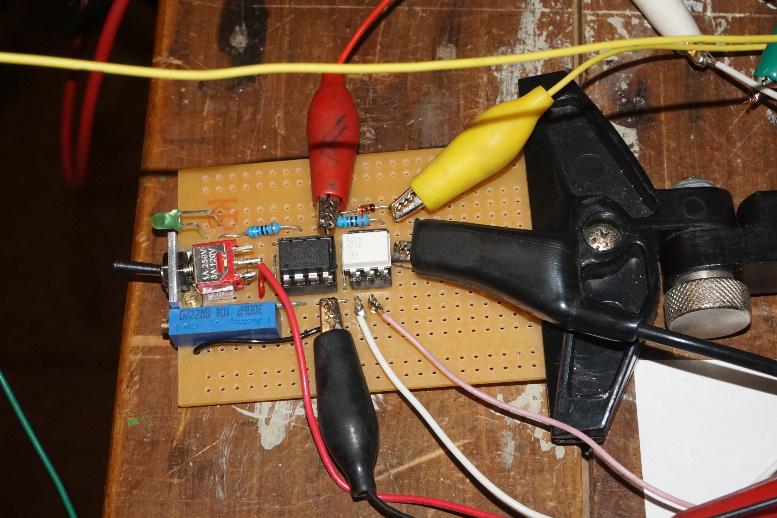
Prototype Stereo Camera Flash Delay using 4N28 optocoupler
Testing – Stereo Camera Flash delay
If all the components are correctly connected, insert the ATtiny85 and optocoupler. Ensure that the chips are installed with the correct pin orientation. Turn on the power! If the activity LED comes on and then flashes every 5 seconds, then the ATtiny85 microcontroller is running. If the activity LED stays on for more than 1.5 seconds upon initial switch on, then you must have missed the vital missing step to change the clock rate to 8MHz. Next, connect a temporary switch with normally open contacts between the Isolation diode (k end) and the circuit ground. Connect your flash with the correct polarity. Switch on the flash and wait for the ready light. Click the temporary switch and the flash should fire!
Testing – High trigger voltage flash interface
The high trigger voltage flash interface should be tested independently from the stereo camera flash delay circuit.
Construct the circuit with all the original resistors values but without connecting 4N28 pins 4 and 5.
Connect the flash. Is the neon indicator working? In some cases, the circuit loading may disable the neon indicator
Measure the voltage across the 270KOhm resistor. Is it below 10volts? Hopefully you will measure a voltage of 10volts or less. If it is more, then the 270K resistor can be changed to a lower value like 220K and measure again.
Connect a temporary switch connect in place where the 4N28 was connected. Operate switch (or simulate switch by touching wires together).
Does the flash fire?
If it fires, let it charge up again. Does the flash fire for the second time? Is the neon indicator still working?
Don't connect to the ATtiny85 yet! Connect a separate 4N28 with pins 4 and 5 to the high trigger voltage flash interface. Connect (pin1) to a 220ohm resistor Connect 4N28 pin2 to negative 3volt supply.
Activate a temporary switch (or touch) +3volt supply on to the other end of the 220ohm resistor that is connected to pin1 of the optocoupler. Flash should fire!
Upon completion of the testing, then connect to the stereo camera flash delay circuit.
Connecting the flash delay circuit to shutter release switch
There are some variations for connecting the stereo camera flash delay to your cameras. The methods shown have both been tested. The first is the conservative approach when using removable multiport plugs. The function of the diodes is to electrically isolate both the cameras and flash delay. Since both cameras and flash delay all operate from a 3 volt sources it is also possible to connect to direct wired cameras as well as shown in the second diagram.
The very conservative way using diode isolation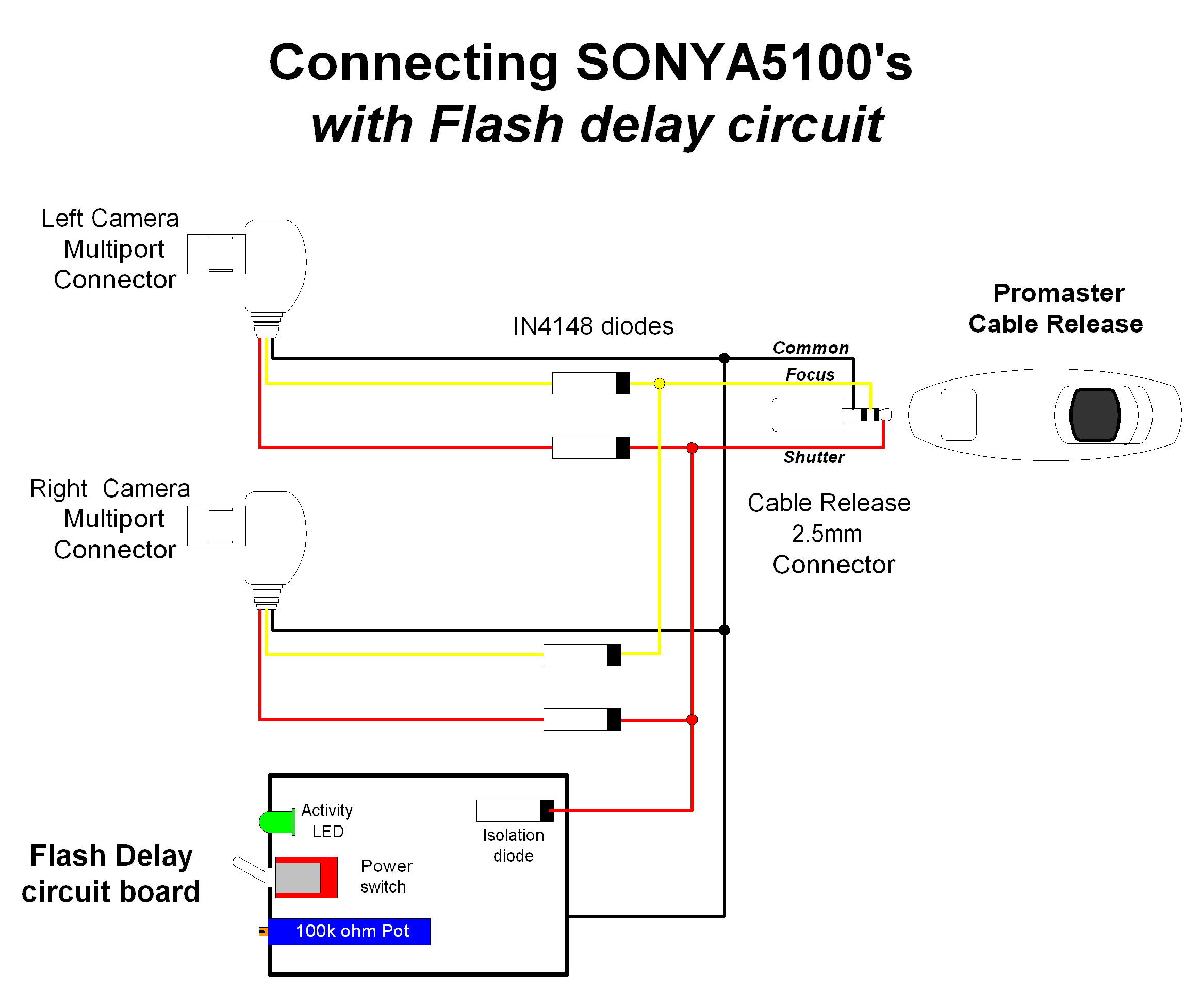
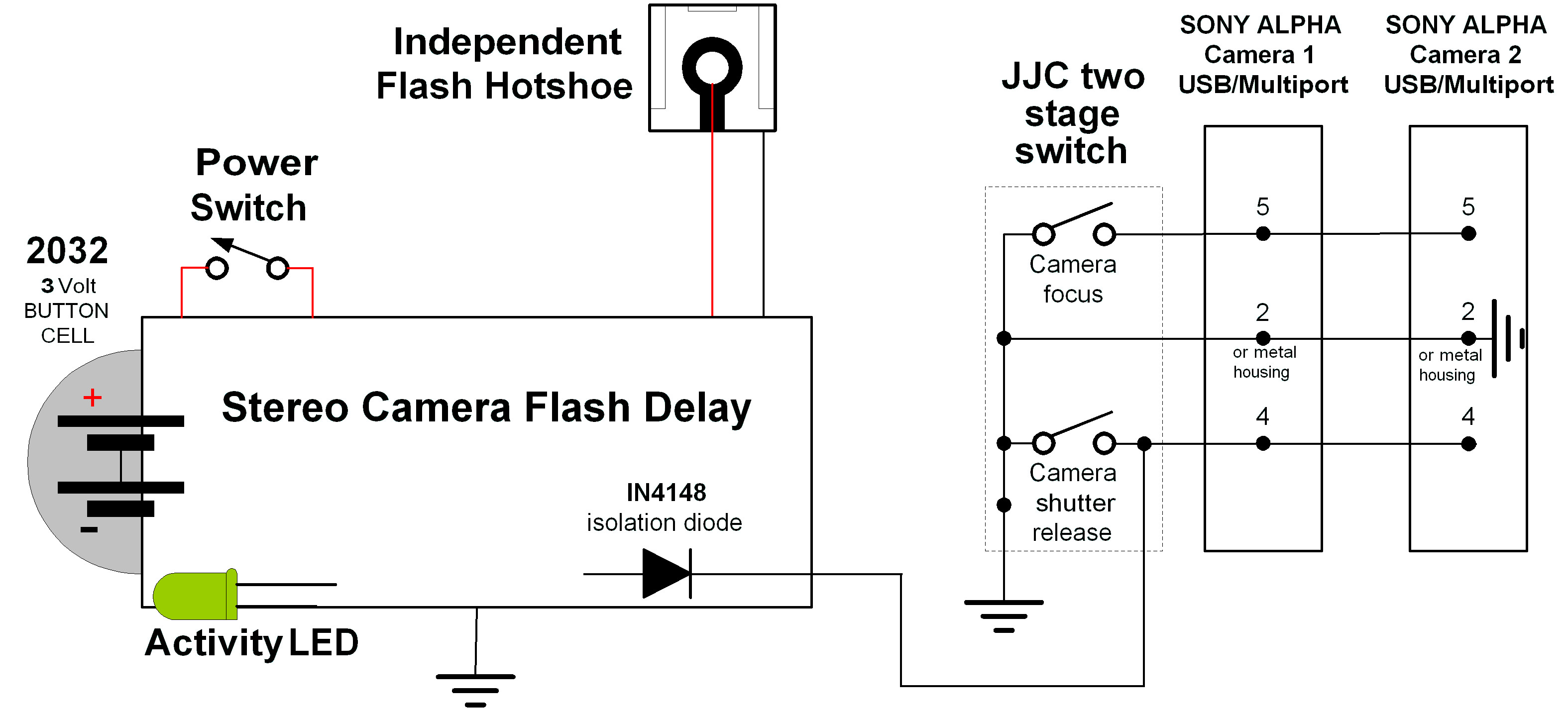
Timo’s connectivity where there is direct wire connection between cameras.
Just for interest, the following diagram is included to explain how a two-stage camera remote switch works. The first part of the diagram shows the contacts when the release button is not pressed. There are no electrical connections between the contacts. The second part shows the contacts that are connected on the first stage of switch operation for focus. There is an electrical contact made between the common wire and the focus signal wire. For many cameras, the common wire is connected to the “ground” of the cameras circuit. The third part shows second stage of operation for shutter release. This is where all three contacts are electrically connected together. The common is connected to both the focus and shutter release signal wires going to the camera.

This example is how contacts operate for a Promaster camera remote
Hardware Options
Activity LED
In the original M-Sync design, this feature was not included. So, it is possible to omit the LED and resistor. But it sure does help when there are bad connections or checking for a depleted battery. Initially even Timo had reservations for its inclusion. But then he had a connection problem with his flash. He connected the activity LED to establish the problem was not with the ATtiny85!
Fixed resistor network for delay timing
If you only plan to use one type of flash, it is conceivable to use a couple of fixed resistors to replace the potentiometer. If you want a very small build, then this may help. It will require some experimentation!
Assuming
that you have found the flash delay time sweet spot, you need to
disconnect the potentiometer before measuring, but making sure you
know which terminals were connected to + and -
To determine the resistance values, use digital multimeter: -
From
the pin connected to negative side of pot to the pots centre pin.
Record value
From
the pin connected to positive side of pot to the pots centre pin.
Record value
Select the best “preferred” resistor values with the combined resistance about 100K ohms
Limitations and issues
Timing variations due to different flash/settings
During testing and development, it was evident that the flash delay range (as set on the potentiometer) may vary according to different power levels set on the flash. When setting the potentiometer, you may have to readjust to find the sweet spot for all the flash power ranges.
Delay Timing variations as battery voltage reduces
There is a small problem with the design when the battery drains and the voltage is reduced. The voltage output from the potentiometer changes. This will impact the flash delay timing. It was found that the delay time reduced by 0.2mS. for a voltage drop from 3 to 2volts. The solution if required, is to use higher voltage power source and use a 3volt regulator as was used by the original M-Sync project.
Problems with the Activity LED
Sometimes the Activity LED can remain on. This was a bug that I could not fix! It is suspected that it may be caused by the fact that the mills command runs on the chips internal interrupts system. It may occur if the activity led flash occurs near a shutter release signal. If it persists, turn the power off and on to reset.
Problems with the high trigger voltage flash interface
There may be an issue with the neon ready indicator on your flash. Depending on the flash design the small power loading of the interface circuit may impact the normal operation of the neon ready indicator. This is due to the interface circuit drawing power from the flash. When testing the disposable camera flash circuit, the neon did not come on! The ready neon on the Sunpak auto114, Metz Mecablitz 34 BCT 2, Metz Mecablitz 303B L23BL flashes operated normally.